I’m not normally one for pedal power. I was given a bike by the next door neighbor when I was a kid. But no sooner had I learned to ride it than I fell off it and knocked myself out. I vowed never to ride a bike again! Whoever thought a two-wheeled vehicle was a good idea anyway?
I still wouldn’t ride a bicycle… But a tricycle might be a different matter.
The Dutch seem to have got the idea about right with their ‘cargo trikes’. It’s possible to buy them here in the UK. There’s even a company in Derby that makes them. But I wanted to build my own for two reasons…
- They are VERY expensive.
- I wanted something vintage looking. Maybe like the old ‘stop me and buy one’ ice-cream trikes.
So over Christmas 2013 a search of E-Bay turned up 2 old bicycles for sale near Skegness. I won them for a little over £20 for the pair and had a drive out to the coast to collect them.
Just one bike would form the basis of the tricycle frame. But as the new machine would have three wheels, the extra wheel was taken from the second bike.
The starting point was a fairly standard gents Raleigh. The frame was cut just ahead of the pedals and also just ahead of the seat, so all I was left with was the triangular section of the back end with back wheel, chain and pedals still attached. This section was then stripped down and an old steel tube I found was welded onto the pedal housing. getting the end of this tube a nice fit to the frame was quite tricky, with much grinding, fitting and grinding again before it was right. However eventually I had the back of a bike with a long tube stuck to the front.

Next I cut the original head tube from the discarded part of the frame and welded this in upside down to the other end of the large tube. This would form the pivot which allows the front end to turn and the bike to be steered. It had to be upside town to allow the two halves of the tricycle to be taken apart again at a later date for maintenance purposes. This head tube was not welded vertically to the main tube, but was set at a slight angle (about 9 degrees off vertical) the opposite way to how a head tube normally is in a bike. This means on the trike the head tube is slightly further forward at the top and points backwards towards the bottom. This is so when the front end of the tricycle is attached it will tilt slightly into corners! I didn’t believe it at first, but I promise it does work!
Next attention turned to the front frame, which was made of steel box section. Some of which was new and some of which was salvaged from a previous existence as a workshop table! An almost square shape was welded together (It’s actually slightly longer than it is wide) then two more longitudinal pieces were welded in to form narrow gaps for the front wheels inboard of the main frame.
The wheels were to be mounted exactly in the middle of this frame and I was advised to put the pivot about 10cm forward of the wheels to help the thing track in a straight line. So I now cut another piece of box section to fit between the two longitudinal inner pieces. Before fitting this last piece to the frame I took the original front forks and inner part of the original head tube and cut off the forks at the point where they become one single tube. The remaining stubby inner head tube was then also turned upside down and welded up vertically to what would be the underside of the last piece of box section I had just cut, care being taken to get it perfectly central. This last piece of box section was then pushed into place between the two inner longitudinal sections to make a tight fit. However before finally welding this piece of box section into place the front frame was assembled to the rear by slotting the upside down inner head tube (I think bike people call it the steer tube) into the upside down head tube.
Now do you remember me saying the head tube was welded to the main tube at a slight angle? Well the fact the steer tube was welded on vertically now meant the front load carrying platform was not parallel with the main tube on the back end of the bike. It actually had a quite pronounced nose down look! Luckily I hadn’t yet welded in the cross piece the inner head tube was welded to, so this cross piece was rotated slightly until both halves of the frame were sitting level in relation to each other.
At this stage 4 small pieces of 4mm thick flat steel were cut and welded to the front frame to make mounting points for the front wheels and all the wheels were then re-attached.

Next two uprights were added at the back of the front frame and to these uprights two short angled sections of box section were added for the ends of the handlebar to fix to.
The handlebar itself was made from a piece of steel tube I had to hand. Itw as a bit rusty, but it will end up pained anyway. This was welded across between the two angled pieces and brake handles plus a bell from the original bike fitted. brake mechanisms were also from the original two bikes. The two front mechanisms being used on the back edge of the two front wheels. The original plan was to mount them on top of the frame, but this was changed when I realised the mechanisms would interfere with the fitting of the cargo box. New brake cables were obtained. Because of the extra length these needed to be, the two front ones are actually Wilko rear cables and each handle controls the brake on the relevant side. However I’ve since found that most trikes have both sets of legally required brakes on the single wheel, which in this case is at the back, to avoid the machine pulling to one side if the brake pressure applied isn’t quite even. The problem is that as yet I’ve not managed to find a cable long enough to connect the rear brake with this design, so at the moment stopping can be a bit interesting to say the least!

Despite the possibility of braking problems, after adding a bracing piece between the seat tube and the main bottom tube, re-fitting chain, pedals and seat, it was time for a test run! This proved to be quite eventful, with a definite ‘knack’ being required to successfully pilot the machine. It was soon found that on cornering the brake levers attached to the handle bar went out of reach as the bar swung sideways. As the front brakes were independent (and the back one wasn’t wired up yet) deploying just the one in reach was a deeply bad idea, so something had to be done.
The solution came by doing two modifications. First, the brake handles were moved more towards the centre of the handle bar. This meant the far one didn’t go quite as far away from the rider when a corner was turned.
The issue of reaching the brakes was also improved by slightly shortening the man tube connecting front to back. It had been noticed that, despite our best efforts, the back end of the tricycle didn’t stand up straight, as it should when pointing in a straight line. Obviously one end of the main tube had been welded on a little twisted. The solution was to cut this tube in half, effectively chopping the trike in two. A short piece of slightly smaller steel pipe was then slotted inside the rear half of the tube and tack welded into place. The plan was then to slot the other end of the new inner-pipe into the front half of the main tube and weld everything back together. But before the front was welded on, the opportunity was taken to chop a couple of inches off the front half and also twist it round a bit, so the back end now stands straight when the front wheels are not turning a corner. I could have just cut the main tube, shortened it a bit and welded it back together. But as this tube takes a lot of stress, the new piece of pipe was added to the inside to bridge the joint and provide extra strength.

With the modifications complete, it was time to take everything apart again and paint the frame. The original back mudguard was rescued from the pile of spare parts and this was also painted and refitted.
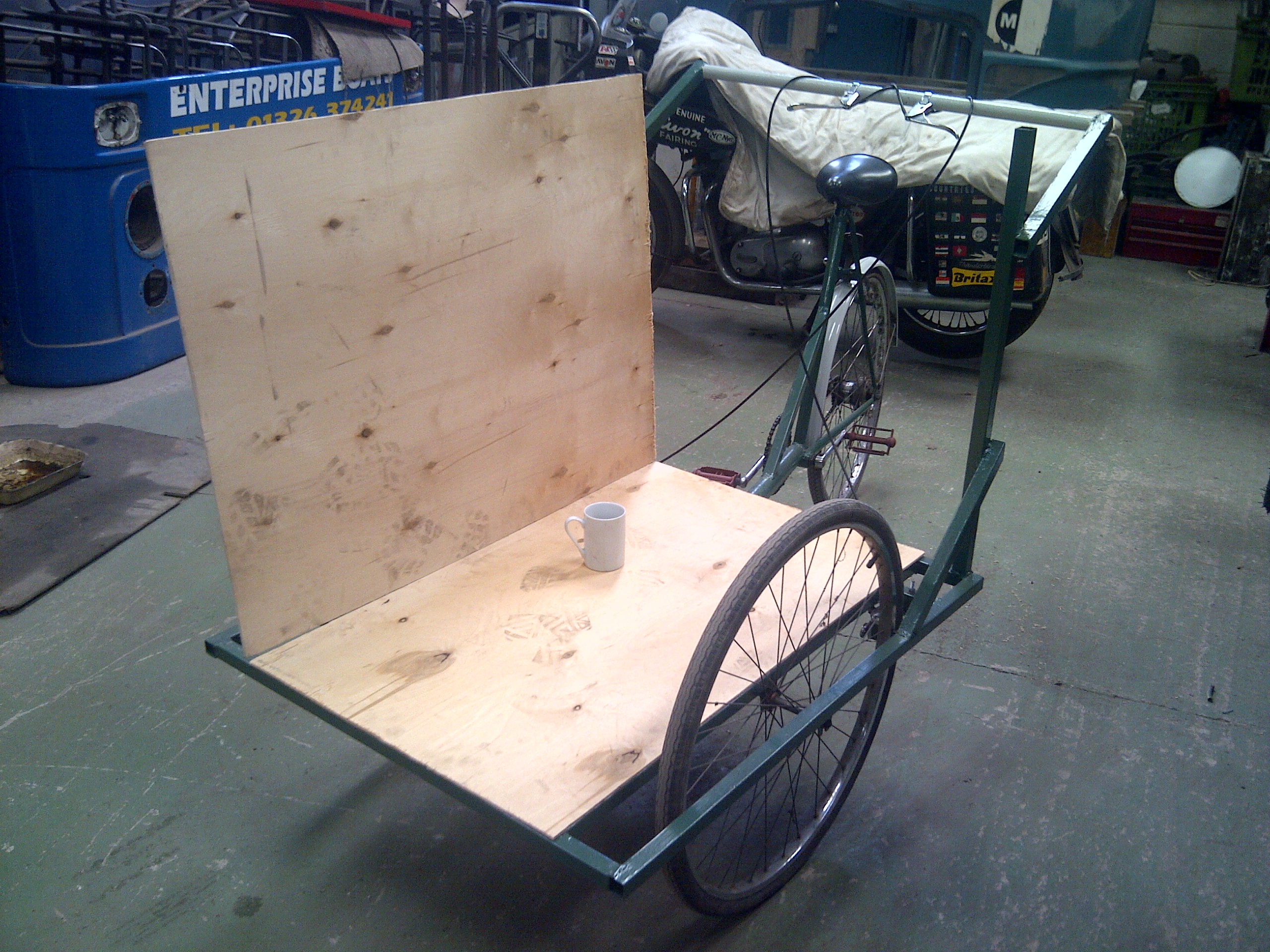
Next attention turned to the construction of the cargo box. This took quite a lot of thinking about and I’m still not entirely happy with the design. How deep should the box be? Should it have a top? Should there be doors in the front? Should there be doors in the back? These were all questions that were asked. It would have been easier to decide on the box if I had a particular final use for the tricycle in mind. But as it was for general use I decided on making the biggest box possible with a removable lid.
One thing that dictated some of the box dimensions was the rider’s ability to see the road ahead. This meant the front edge of the box could not be above a certain height, which was worked out with a bit of trial and error. I also wanted plenty of space on the box to sign write some advertisements etc in the future. Remembering the design of old ice-cream trikes, I recalled that they often had a sign on the top edge of the box, effectively extending the height of the sides. I decided on a modified version of this, using one large piece of plywood for each side, which extended higher than the top of the front. The back was also made the same height as the sides. The removable lid then fitted between the sides and back, with it’s front edge at the same level as the top of the front panel. I also considered sloping the lid so water would run off forwards, but decided against this just in case I wanted to use the trike for selling things and I wanted to lay stock out on the top of the box. However I have since decided this is not the best design for a sales box. It would be far better to have a fixed top and a door in either the front or the back to access stock inside without disturbing the display on the top. So the box may yet be modified.
Around the time I was thinking about making the box I was also given the remains of a very large wooded packing crate. These panels, when taken apart, yielded more than enough 6mm plywood to construct the box. All I had to buy were some wood strips to fit inside the corners of the box, which the plywood panels were then screwed to. The box is exactly the same length as the front frame base. The back and front of the box extend about an inch below the box bottom, so when it’s placed on the frame it can’t move either backwards or forwards. It can still move sideways, but a couple of wood strips under the floor would also stop it from sliding left or right. However this hasn’t been a problem as yet, so these strips still remain to be fitted. The great feature of this design is that the box can simply be lifted off and replaced with a different one if a different use is required.
With the box complete, the exterior was primed and then given a coat of white gloss to protect it from the elements. Particular attention was given to the underside, which will likely get a lot of spray and dirt kicked up by the front wheels. The colour of the box will probably change eventually, but for now the gloss has sealed it nicely while I decide what the sign-writing will be.
